





Blog

What Is a Heavy Lift Drone Frame and How Does It Work?

A Heavy Lift Drone Frame is the structural foundation of an aircraft designed to carry substantial payloads safely and repeatedly. It connects motors, batteries, flight controllers, landing gear, and payload systems. More importantly, it manages every force created during flight.

Market demand is rising. MarketsandMarkets projects the drone logistics and transportation market to grow from approximately USD 8.5 billion in 2023 to USD 32.7 billion by 2028. That growth increases pressure on manufacturers to build lighter, stronger, and easier-to-maintain platforms. However, the frame itself is often overlooked.

That is a mistake.

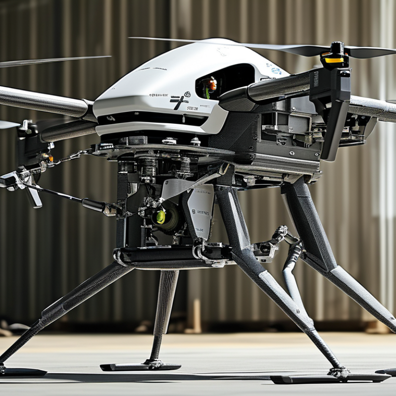
A heavy-lift frame usually combines carbon-fiber plates, aluminum joints, reinforced arms, and vibration-damping mounts. Motors generate upward thrust through the arms. The central body distributes payload weight across the structure. Landing gear protects the load during touchdown. Small design choices matter. A loose motor mount can create vibration, heat, and unstable flight.

Raffaello D’Andrea, a leading robotics researcher and autonomous-flight designer, has stated, “The goal is to make robots that are useful, safe, and beautiful.” His principle fits heavy-lift engineering well. A capable frame must perform reliably, not merely look impressive.

Reports from the Federal Aviation Administration and Drone Industry Insights also emphasize operational safety, fleet reliability, and evolving commercial drone use. Yet published market figures rarely isolate the frame segment. That limitation deserves attention.

This article explains how a Heavy Lift Drone Frame works, from load paths and thrust balance to material selection, fatigue resistance, and real-world maintenance. The engineering is advanced. The lesson is simple: carrying more requires controlling every gram, vibration, and connection.
What Is a Heavy Lift Drone Frame and How Does It Work?

Defining Heavy-Lift Drone Frames: 25–150 kg Payloads and MTOW

A heavy-lift drone frame is the structural platform built to carry substantial external or internal loads. In this context, heavy lift commonly means a payload between 25 and 150 kilograms. Payload is not MTOW. Payload includes cargo, containers, sensors, and sometimes delivery equipment. MTOW means the drone, batteries, propulsion system, payload, and landing gear combined. A 25-kilogram payload drone may weigh 60 kilograms at takeoff. A 150-kilogram payload design can exceed 300 kilograms, depending on its architecture.

The frame transfers motor thrust through arms, joints, and the central body. Carbon-fiber tubes, aluminum fittings, and reinforced plates reduce bending during acceleration. Multiple motors improve stability after a propulsion fault, but they also increase battery demand. The International Energy Agency reported that lithium-ion battery pack prices reached about 139 US dollars per kilowatt-hour in 2023. That figure matters because energy storage often limits practical payload more than frame strength. Heavy loads need large landing supports. They also need careful center-of-gravity control.

Drone Industry Insights estimated the commercial drone market at approximately 30.6 billion US dollars in 2024. This growth supports demand for industrial lifting platforms, yet market labels remain inconsistent. A “150-kilogram frame” may describe maximum payload, not tested operating capacity. That difference deserves scrutiny. Operators should check structural load tests, hover endurance, vibration data, and battery performance at realistic temperatures. A frame that lifts once is not necessarily reliable for repeated work. Real experience is less tidy. Weather, uneven loading, and aging batteries can quickly reduce the advertised margin.

Frame Architecture: Carbon-Fiber Arms, 6–8 Motors, and Redundant Load Paths

A heavy lift drone frame is a structural system, not merely a platform for motors. Carbon-fiber arms provide high stiffness with low mass. This matters when every gram affects payload and flight endurance. A 2024 FAA Aerospace Forecast projects the U.S. commercial small-drone fleet could reach about 1.18 million aircraft by 2028. More aircraft will demand stronger, more inspectable frames.

Most heavy-lift designs use six or eight motors. Six motors can reduce weight. Eight motors offer better control after a single motor or propeller failure. The frame should also include redundant load paths. Forces should travel through multiple arms, center plates, fasteners, and landing supports. If one joint cracks, another path must carry the load temporarily. Carbon fiber can hide internal damage, however. A clean surface may still contain delamination. That is easy to underestimate.

Tips: Inspect arm roots, bolt holes, and center plates after hard landings. Use torque records, not memory. Check cable clearance near moving arms. ASTM F38 structural guidance supports disciplined inspection and test planning, but it cannot replace flight testing. In practice, perfect symmetry is rare. I would leave a safety margin above the calculated payload, then test with incremental weights. The design may look overbuilt. That is often acceptable.

What Is a Heavy Lift Drone Frame and How Does It Work? — Frame Architecture: Carbon-Fiber Arms, 6–8 Motors, and Redundant Load Paths

Design Dimension Typical Configuration or Data How It Works Engineering Consideration
Frame Layout Flat central body with six or eight radial arms Loads from the motors, landing gear, batteries, and payload are transferred through the arms into the central frame plates. A symmetrical layout helps balance the center of gravity and distributes thrust around the airframe.
Number of Motors 6 or 8 motors Multiple motors generate vertical thrust and allow the flight controller to control roll, pitch, and yaw by changing individual motor speeds. An eight-motor arrangement generally provides more actuator redundancy than a four-motor arrangement, but it adds mass, wiring, and control complexity.
Arm Material Carbon-fiber tubes or molded carbon-fiber members Carbon fiber provides high stiffness and strength at relatively low mass, helping the arms resist bending and vibration. The fiber direction, tube diameter, wall thickness, joint design, and local impact damage are often more important than the material name alone.
Arm Cross-Section Round, square, or rectangular hollow sections Hollow sections place material away from the neutral axis, increasing bending stiffness without using a solid block of material. Round tubes resist torsion well, while rectangular sections can simplify motor-mount and frame-joint interfaces.
Central Load-Bearing Structure Two or more separated structural plates with spacers and bonded or bolted joints The upper and lower plates form a rigid load path for arm reactions, battery loads, payload forces, and landing impacts. Spacing between plates increases bending stiffness, but fastener holes and cut-outs must be checked for stress concentration.
Redundant Load Paths Independent arm attachments, paired plates, cross-braces, and multiple fasteners If one fastener, clamp, or local attachment is damaged, secondary members can help retain the arm and limit progressive structural failure. Redundancy must be demonstrated by structural analysis and testing; simply adding more parts does not guarantee fail-safe behavior.
Thrust-to-Weight Ratio Common design target: approximately 2:1 maximum total thrust to takeoff weight Available thrust above hover provides control authority for maneuvering, wind compensation, and changes in payload or battery condition. The required margin depends on operating altitude, temperature, propeller selection, battery voltage, and the intended flight profile.
Payload Integration Payload mounted close to the center of gravity Keeping the payload near the center reduces the control moments that the flight controller must overcome. A low-mounted payload may improve stability but must maintain ground clearance and avoid interfering with landing gear or airflow.
Motor Mounts Rigid plates or brackets secured to the ends of the arms Motor mounts transfer thrust, torque, and vibration into the arm structure while maintaining propeller alignment. Mounts should be checked for bolt pull-through, local crushing, fatigue, and loosening under repeated motor torque.
Vibration Management Rigid arms with controlled isolation for flight electronics The frame carries motor loads while isolation elements reduce high-frequency vibration reaching inertial sensors and cameras. Excessive flexibility can create resonances, while excessive isolation can allow sensor motion or control-loop instability.
Landing Gear Interface Wide stance with direct attachment to the central frame or dedicated lower members Landing gear transfers impact and static ground loads into the main structure during touchdown and while carrying a payload on the ground. The gear should prevent propeller contact with the ground and avoid creating a large bending moment in a single frame plate.
Structural Safety Factor Often selected above 1.5 for ultimate static loads, subject to the applicable design standard The safety factor separates the predicted design load from the estimated failure load to account for uncertainty and variation. Fatigue, impact, composite delamination, fastener failure, and manufacturing defects require separate evaluation.
Mass Distribution Concentrated heavy components near the center; arms kept light Lower rotational inertia allows the aircraft to respond more efficiently to control inputs, while central mass reduces arm bending loads. Battery placement should also support the intended center-of-gravity range as the state of charge changes.
Inspection Points Arm roots, motor mounts, fastener holes, plate edges, and payload attachments These areas experience high stress, vibration, or impact and are common locations for cracks, loosening, delamination, or crushing. Inspection intervals should be based on flight hours, landing cycles, operating environment, and any abnormal event.

Lift Mechanics: Why Thrust-to-Weight Ratios Above 2:1 Improve Stability

A heavy lift drone frame is the structural foundation for carrying cameras, sensors, or industrial tools. It connects the motors, flight controller, battery, landing gear, and payload mounts. Its arms must resist bending and twisting during acceleration. A rigid frame also helps reduce vibration reaching sensitive electronics.

Thrust-to-weight ratio compares the drone’s maximum combined thrust with its loaded weight. A 2:1 ratio means the motors can produce twice the force needed for hovering. That margin matters. The aircraft can climb without operating near full power. It can also correct its position faster when wind pushes against the payload. During a sudden tilt, extra thrust helps maintain altitude and control authority.

A simple ratio can mislead. Real thrust falls as batteries discharge, propellers collect dust, or motors heat up. Payload placement matters too. An off-center load may create continuous torque, forcing the flight controller to work harder. Practical testing should measure thrust with the actual propellers, battery, frame, and payload installed. Static bench results are useful, but they cannot reproduce every gust or vibration pattern.

Frame weight creates a difficult trade-off. Thicker arms may improve stiffness, yet they also increase the lift required for flight. In field testing, a stable platform usually comes from balanced design rather than maximum motor power. More thrust is helpful, but poor tuning, flexible joints, or loose fasteners can still produce uneven movement. It is not magic.

Power Systems: 12S–24S Batteries, 10–30 Minutes of Typical Flight

A heavy lift drone frame supports larger motors, batteries, landing gear, and useful payloads. Its structure must resist twisting during acceleration and braking. Carbon tubes, reinforced plates, and isolated mounting points help distribute these forces. A flexible frame can waste energy and blur camera footage. It may also stress motor arms over time.

Power systems commonly use 12S to 24S battery configurations. A 12S pack offers lower voltage demands for compatible components. A 24S system can deliver similar power with less current. Lower current may reduce cable heating and electrical losses. However, higher voltage requires careful insulation, connectors, and component matching. One mistake can damage expensive hardware.

Flight time usually ranges from 10 to 30 minutes. Payload weight, wind, battery age, and hover throttle change that number quickly. A large battery adds energy, but it also adds mass. My early estimates would have been too optimistic without measuring real current draw. Bench tests are useful, yet they cannot fully reproduce wind or repeated climbs. Leave reserve capacity for landing, unexpected headwinds, and battery voltage sag. Heat is unforgiving. A practical design checks motor temperature, battery temperature, and voltage under load. The frame, propulsion system, and payload must be evaluated together, not separately.

Heavy Lift Drone Power Systems: 12S–24S Batteries

Typical flight time decreases as battery voltage and system power increase. The ranges below represent common heavy-lift configurations using comparable payloads, propeller sizes, and reserve margins.

Nominal voltage is calculated at 3.7 volts per lithium-polymer cell: 12S equals 44.4 V, while 24S equals 88.8 V. Actual endurance varies with payload, motor efficiency, propeller selection, wind, battery capacity, and landing reserve.

Structural Validation: 1.5× Load Factors, Vibration Tests, and Fail-Safes

What Is a Heavy Lift Drone Frame and How Does It Work?

A heavy lift drone frame supports larger motors, batteries, payloads, and landing forces. Its structure must remain stiff without becoming unnecessarily heavy. Engineers often use reinforced arms, wide mounting plates, and carefully placed joints. A small crack near a motor mount can grow quickly under repeated stress. I have seen vibration expose weaknesses that static measurements missed.

Structural validation should begin with a 1.5× load factor. If the expected payload weighs 20 kilograms, the frame should withstand 30 kilograms during controlled testing. This margin reflects acceleration, hard landings, and uneven weight distribution. Testers should inspect arm deflection, fastener movement, and joint deformation. Vibration tests matter too. They can reveal resonance near motor operating speeds. In practice, a frame may pass a weight test yet develop loose screws after several minutes. That result deserves investigation, not excuses. Fail-safes should include secure payload retention, separated power paths, and landing support that protects critical components. Each feature needs a practical test record.

Tips: Apply loads gradually. Use calibrated sensors and protective barriers. Check joints before and after every test. Record unusual sounds, heat, or movement. Do not treat a clean first result as final proof. Materials vary, and assembly errors happen. A cautious retest often provides better evidence than confidence.